 EN
EN


 English
 русский
 日本語
日本語 Español
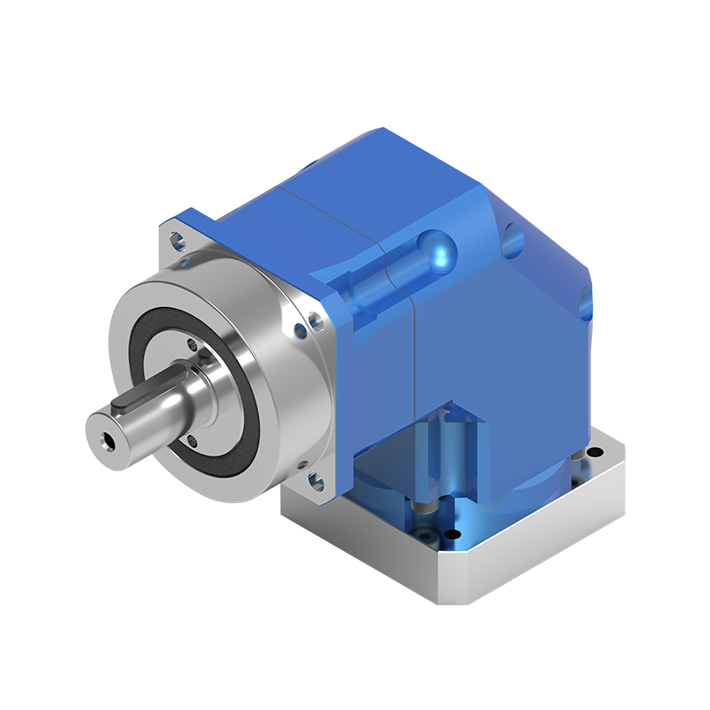
Low Noise Multi specification Integrated-Structure Planetary Reducer AHS Series
Cat:Planetary Reducer
Planetary reducers occupy an important position in the field of industrial automation. The high-prec...
See DetailsContent
At the heart of many powerful and compact transmission systems lies the planetary gear set, also known as an epicyclic gear train. This ingenious arrangement of gears is fundamental to the operation of a planetary drive. Its name is derived from its resemblance to a solar system, where a central "sun" gear is surrounded by "planet" gears, all contained within an outer "ring" gear. This compact and robust configuration is the source of its remarkable capabilities in torque transmission and speed variation.
To fully grasp the working principle, one must first understand the function of each component within the planetary gear set. The system's elegance lies in the interplay between these key parts.
The operational magic of a planetary gear set stems from the ability to hold one component stationary, apply input power to a second component, and extract output from the third. This flexibility allows for different speed ratios and rotational directions without the need to engage or disengage other gears, enabling smooth and seamless transitions. For instance, by holding the ring gear and driving the sun gear, the planet gears are forced to "walk" along the stationary ring, causing the planet carrier to rotate in the same direction as the sun gear but at a reduced speed and higher torque. This is a classic configuration for a speed reducer. Conversely, by holding the carrier and driving the sun gear, the planet gears act as idlers, causing the ring gear to rotate in the opposite direction, achieving a reverse gear. This kinematic versatility is what makes understanding planetary gear set configuration options so critical for engineers designing complex drive systems.
The widespread adoption of planetary drives across various industries is a direct result of their compelling set of advantages over other types of gear systems. These benefits make them indispensable in applications where performance, reliability, and space are critical constraints.
One of the most significant benefits is their high power density. Because the input power is divided among several planet gears, the load is shared across multiple contact points. This distribution means that planetary systems can transmit substantial amounts of torque in a very compact package. Compared to a standard parallel-shaft gearbox of similar torque rating, a planetary gearbox will typically be significantly smaller and lighter. This makes them ideal for applications like electric vehicle transmissions, where space and weight are at a premium, but high torque from the electric motor is a necessity.
The nested, concentric design of planetary gears results in a very compact form factor. The input (sun) and output (carrier or ring) share the same central axis, leading to a coaxial shaft arrangement. This is a major design advantage as it simplifies the overall mechanical layout, eliminating the need for offset shafts and additional components like couplings or belts to transfer power between parallel axes. This inherent compactness is a primary reason why they are the gearbox of choice in applications ranging from industrial mixers to aircraft engine accessories and construction machinery.
Planetary gear systems are renowned for their high efficiency, often exceeding 97% per stage under optimal conditions. The reason for this is twofold. First, the power loss is minimized due to the rolling contact and the distribution of the load among several planet gears. Second, because multiple planet gears share the load, the forces on individual gear teeth are lower, which reduces friction and wear. This even load distribution also contributes to exceptional durability and a long operational life, even under demanding and continuous duty cycles. This high efficiency is a key factor for applications focused on energy savings, such as in wind turbine pitch control systems or high-precision industrial robotics.
The true versatility of the planetary gear system is unlocked through its various configurations. By selectively choosing which component is the input, which is the output, and which is held fixed, a wide range of gear ratios and rotational directions can be achieved. This section explores the most common setups and their typical uses, providing insight into applications for planetary gearboxes across different sectors.
This is the most frequent application of planetary gears. In this setup, the input is applied to the sun gear, the ring gear is held stationary (fixed to the housing), and the output is taken from the planet carrier. This results in a reduction in output speed and a proportional increase in output torque. The gear ratio is determined by the number of teeth on the sun and ring gears. This configuration is the workhorse of industry, found in conveyor drives, crane hoists, and the wheel drives of heavy mining equipment, where high torque at low speeds is required.
An overdrive increases output speed while decreasing torque. This is achieved by using the planet carrier as the input, the sun gear as the output, and keeping the ring gear stationary. While less common than the reducer, this configuration is crucial in automotive automatic transmissions to allow the engine to operate at lower RPMs at high vehicle speeds, thereby improving fuel efficiency.
To achieve a reversal in the direction of rotation, the planet carrier is held stationary. Input is provided to the sun gear, and output is taken from the ring gear. The planet gears, acting as idlers, cause the ring gear to rotate in the opposite direction to the sun gear. This is the fundamental principle behind the reverse gear in automotive transmissions and is also used in various winching and traversing mechanisms.
Designing a reliable and efficient planetary drive system is a complex engineering task that involves balancing numerous factors. A successful design must meet performance targets for torque, speed, and life while operating within physical constraints. For those involved in the process, understanding the design considerations for planetary gear systems is paramount to avoiding common pitfalls and achieving optimal performance.
The heart of the design lies in the gear teeth. Engineers must perform rigorous calculations to ensure the teeth can withstand the bending stresses and contact (Hertzian) stresses imposed by the transmitted torque. Key factors include:
Furthermore, the number of planet gears is a critical decision. While three planets are common, using four or more can further increase torque capacity and improve load sharing, but it also complicates the manufacturing and assembly of the planet carrier.
Effective lubrication is non-negotiable for the longevity and efficiency of a planetary drive. It serves three primary purposes: reducing friction and wear, removing heat, and protecting against corrosion. The choice between oil splash, forced oil circulation, or grease lubrication depends on the operating speed, load, and environmental conditions. High-speed applications generate significant heat from windage and friction, making thermal management a key design challenge. Inadequate cooling can lead to oil breakdown, loss of lubricity, and ultimately, premature failure of gears and bearings. Designers must ensure sufficient cooling, sometimes incorporating external heat exchangers or cooling fins on the housing.
The planet carrier is a critically stressed component. It must be rigid enough to maintain precise alignment of the planet gears under full load to ensure equal load sharing. Any deflection can cause one planet to carry a disproportionate amount of the load, leading to its premature failure. The bearings supporting the planet gears are also subjected to complex loading. They must accommodate high radial loads from the gear meshing forces as well as potentially significant overturning moments. Selecting the correct bearing type—often cylindrical roller bearings or tapered roller bearings—and accurately calculating its life are essential steps in the design process to ensure the system meets its reliability goals.
While planetary drives offer numerous benefits, they are not the only gear system available. Understanding their performance relative to other common types, such as parallel-shaft helical gears and worm gears, is crucial for selecting the right technology for a given application. This comparative analysis highlights the trade-offs an engineer must consider.
The following table provides a direct comparison based on several key performance and design parameters. It is important to note that these are general trends and specific designs may vary.
| Feature | Planetary Gear System | Parallel-Shaft Helical Gears | Worm Gear System |
|---|---|---|---|
| Power Density | Very High. Load is shared across multiple planet gears. | Moderate. Load is borne by a single gear mesh per stage. | Low to Moderate. The sliding contact limits power transmission. |
| Efficiency | Very High (often >97% per stage). Primarily rolling contact. | High (95-98% per stage). Rolling contact with some sliding. | Low to Moderate (50-90%). Dominated by sliding friction, especially at higher reduction ratios. |
| Coaxial Input/Output | Yes. A key design advantage for compact layouts. | No. Input and output shafts are parallel and offset. | No. Input and output shafts are typically at 90 degrees. |
| Ratio per Stage | High. Ratios of 3:1 to 12:1 are common in a single stage. | Moderate. Typically limited to around 1:1 to 10:1 per stage. | Very High. Single-stage ratios can easily exceed 50:1. |
| Back-Driving | Generally reversible. Output can drive the input. | Generally reversible. Output can drive the input. | Often self-locking. The worm can drive the wheel, but the wheel cannot drive the worm at high ratios. |
| Complexity & Cost | High. More components and tighter tolerances required. | Low to Moderate. Simpler design and manufacturing. | Moderate. The worm screw can be complex to manufacture. |
As the table illustrates, planetary systems excel in applications demanding high torque and power in a small, efficient package with coaxial shafts. However, this comes at the cost of higher complexity and a higher initial price point. In contrast, parallel-shaft gears are a robust and cost-effective solution for less space-constrained applications. Worm gears are unmatched for achieving very high single-stage reduction ratios and providing a built-in braking feature due to their potential for self-locking, but their low efficiency can be a major drawback. This comparison is vital for anyone looking to understand the benefits of planetary gear reducers in the context of the broader gear market.
Ensuring the long-term health and reliability of a planetary drive requires a proactive approach to maintenance and a keen eye for early signs of trouble. A well-executed maintenance strategy can prevent costly unplanned downtime and extend the operational life of the equipment significantly. This section outlines best practices and common issues, forming a guide for troubleshooting planetary gear drive issues.
A preventative maintenance program is the first line of defense against premature failure. This program should be systematic and based on the manufacturer's recommendations, adjusted for the specific operating conditions.
When problems do arise, being able to diagnose the issue correctly is crucial. Most failures in planetary gearboxes are symptomatic of a few root causes.
By integrating a robust maintenance plan and understanding these common failure modes, operators can significantly improve the reliability of their planetary drive systems and effectively manage their lifecycle costs, ensuring they reap the long-term benefits of planetary gear reducers.

Planetary reducers occupy an important position in the field of industrial automation. The high-prec...
See Details
The planetary reducer adopts a helical gear design, which enables smooth and quiet operation and pro...
See Details
Features of planetary reducer1. Quiet: Use helical gears to achieve smooth and quiet operation;2. Hi...
See Details
Features of planetary reducer1. High precision: the standard backlash is 4 arc minutes, which is ver...
See Details
The TD-CR series reducer is centered on the design of hollow shaft output, which not only optimizes ...
See Details
● Various output shaft options● High torque● High efficiency● Long service life● Low backlash● Maint...
See Details
Innovative helical gear structureThe reduction mechanism introduces an innovative helical gear desig...
See Details
The NLR series planetary reducer adopts a spiral bevel gear design, which allows high-speed input of...
See Details
The BCSG series Flexible gear reducer is designed to be light and simple, which not only effectively...
See Details
BSHF series Flexible gear reducer adopts a large-diameter hollow shaft design with a compact structu...
See Details
