 EN
EN


 English
 русский
 日本語
日本語 Español
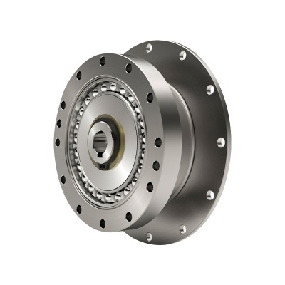
Low Noise Durable Servo Motor Speed Planetary Reducer AHT series
Cat:Planetary Reducer
With its high-precision characteristics, the planetary reducer successfully controls the backlash wi...
See DetailsContent
A harmonic reducer—often called a strain wave gearbox—uses a flexible cup (flexspline), a rigid ring with internal teeth, and an elliptic wave generator to achieve reduction ratios that are unusually high for the size and mass of the unit. When the wave generator deforms the cup, only two lobes of the flexspline engage the ring at any instant, and because the flexspline has slightly fewer teeth than the ring, every rotation of the wave generator advances engagement by a tooth count difference, producing large reduction. This geometry concentrates contact in moving zones, which spreads wear over many teeth and contributes to smooth meshing. The result is an actuator stage that delivers exceptional positioning precision with low backlash, excellent torsional stiffness, and repeatable motion even under reversing loads.
In conventional gear trains, backlash arises from clearance between rigid teeth. In a strain wave reducer, elastic deformation and circumferential tooth wrap produce an almost preloaded contact that dramatically minimizes free play. For applications requiring arc-minute or sub-arc-minute repeatability—such as camera gimbals, semiconductor handling, or surgical robotics—this characteristic becomes a decisive advantage. A precision harmonic reducer low backlash configuration helps hold position against torque disturbances and micro-vibrations that would otherwise accumulate as contouring error, allowing the control loop to use higher gains without exciting oscillations.
Efficiency depends on ratio, lubrication, and load; typical values are competitive with compact planetary stages at moderate ratios, though very high ratios may show slightly more internal flex losses. Axial and radial stiffness are shaped by bearings and case geometry, while torsional stiffness reflects the flexspline wall thickness and tooth engagement arc. Lifecycle is strongly tied to proper lubrication and temperature management; elastically stressed flex components can run for many thousands of hours if operated inside specified torque and speed envelopes. Designers should consider duty cycles with frequent start-stop and reversing motion, because the strain field in the flexspline rotates with the wave generator and must be kept below fatigue limits.
Harmonic reducers excel when you need compact size, high ratios in one stage, low mass, very low backlash, and consistent accuracy across the service life. They are a natural fit for articulated joints, pan-tilt heads, precision indexing, and collaborative robot wrists. If the application involves continuous high-speed rotation with heavy shock loads or demands extremely high input speeds, designers may pair the reducer with an upstream belt stage or consider alternate architectures. Still, in the majority of medium-speed, high-precision tasks, the strain wave approach yields best-in-class volumetric efficiency and accuracy per kilogram.
A robust sizing process begins by mapping all external torques: static gravity torque from the payload and link, dynamic acceleration torque from desired motion profiles, friction and seal torques, and disturbance torques like cable drag. Add safety factors for uncertainty and include duty cycle. The core objective is to ensure the reducer can transmit peak and RMS torques without excessive heating or fatigue. The ratio is then selected to keep the servo motor operating in a favorable speed–torque region while meeting resolution targets. Because harmonic reducers offer very high single-stage ratios, you can often choose a smaller motor without compromising accuracy, provided the reducer’s allowable input speed is respected.
Consider a wrist joint with a 2.5 kg tool at a 0.25 m radius, targeting 300 °/s with rapid reversals. Gravity torque at worst pose is roughly 2.5·9.81·0.25 ≈ 6.13 N·m. Suppose acceleration adds 3.5 N·m and friction another 0.4 N·m. With a safety factor of 1.6, required output torque becomes (6.13 + 3.5 + 0.4)·1.6 ≈ 16.7 N·m. Choose a ratio that lets the motor deliver this after reduction while keeping input speed under limits and ensuring reflected inertia is manageable for control. Finally, verify continuous torque at the joint’s RMS duty so thermal limits are respected over the mission profile.
| Parameter | Symbol | Value | Notes |
|---|---|---|---|
| Payload mass | m | 2.5 kg | Tool plus adapter |
| Lever arm | L | 0.25 m | From axis to CoM |
| Gravity torque | Tg | 6.13 N·m | Worst pose |
| Acceleration torque | Ta | 3.50 N·m | Based on motion profile |
| Friction torque | Tf | 0.40 N·m | Seals, bearings, cable drag |
| Safety factor | SF | 1.6 | Includes uncertainty |
| Required output torque | Treq | 16.7 N·m | Design target |
The above workflow embodies the spirit of harmonic reducer torque calculation: quantify, margin, verify thermal behavior, and iterate ratio until the actuator hits speed, stiffness, and accuracy goals without oversized components.
A multi-axis arm typically features decreasing torque requirements from base to wrist; however, accuracy demands often increase toward the end effector. When selecting a harmonic reducer for robotic arm joints, the base may favor higher torque and stiffness for positional stability under long links, while the wrist demands minimal backlash and low mass for agility. The reducer’s compact axial dimension helps keep the arm’s center of mass close to each axis, reducing required counter-torque and improving energy efficiency across duty cycles with frequent starts and stops.
Because the reducer ratio multiplies motor torque and divides speed, it also increases reflected load inertia by the square of the ratio as seen by the motor. Striking a balance between high ratio for resolution and modest ratio for controllability is essential. Excessive reflected inertia can force conservative control gains and lengthen settling time. The torsional compliance of the reducer should be factored into the servo model; too little stiffness can couple with load inertia and create lightly damped modes, whereas a stiffer configuration supports higher bandwidth and sharper path tracking without overshoot.
Industrial cells expose joints to temperature swings, dust, and occasional impacts. Select sealing and lubrication compatible with the environment and maintenance plans. If the arm experiences frequent tool changes, consider additional safety margin for transient torques during docking. For vertical axes that must hold load during power loss, integrate a brake or choose a reducer with low internal backdrivability to limit fall distance while the brake engages.
| Joint | Primary Concern | Typical Ratio | Notes for Harmonic Reducer |
|---|---|---|---|
| Base (J1) | High torque & stiffness | High–very high | Watch input speed limits; ensure strong bearings |
| Shoulder/Elbow (J2–J3) | Mixed torque & speed | Medium–high | Balance inertia with ratio for dynamic moves |
| Wrist (J4–J6) | Low backlash & low mass | Medium–high | Prioritize precision harmonic reducer low backlash |
Collaborative robots share workspaces with people and thus prioritize smooth, inherently safe dynamics. A compact harmonic reducer for cobot delivers high reduction in a small envelope, aiding lightweight arms that limit inertia and impact energy. The smooth, near-zero backlash engagement supports high-resolution torque estimation for collision detection, while compactness allows actuators to be tucked into slim link profiles that are easier to shield and round for safety.
Cobots benefit from joints that can be backdriven with reasonable torque so that the system can detect and respond to unexpected contact. Harmonic reducers vary in apparent backdrivability depending on ratio and seal friction; selecting moderate ratios and optimized lubrication helps. Because cobots often run at lower speeds with frequent human interaction, thermal headroom and continuous torque—not just peak—should be verified. Low cogging motors paired with reducers that minimize stiction improve small-force control, enabling compliant assembly and hand-guiding modes.
While collaborative payloads may be modest, long reaches and extended horizontal poses can still generate meaningful gravity torque. The reducer must be sized for worst-case posture while accounting for safety functions like power and force limiting that may derate maximum allowable speeds. Designers should model common tasks—bin picking, machine tending, light screwdriving—to determine the true RMS torque and ensure the reducer’s thermal rating is not exceeded during continuous collaborative operation.
| Aspect | Cobot Priority | Industrial Arm Priority | Implication for Harmonic Reducer |
|---|---|---|---|
| Safety | Contact sensitivity | Throughput & rigidity | Favor smooth low-friction designs for cobots |
| Weight | Minimal actuator mass | Less constrained | Use compact, high ratio units close to joints |
| Duty cycle | Long, low-speed interaction | High-speed cycles | Check continuous torque & temperature rise |
| Control | Impedance & force control | Position accuracy | Low stiction and precision harmonic reducer low backlash |
Both strain wave and planetary transmissions can deliver high ratios and torque density, but their behaviors differ in ways that affect application suitability. Harmonic units emphasize ultra-low backlash, compact axial length, and high single-stage ratios, making them excellent for precision joints and compact wrists. Planetary stages typically offer higher input speed capability, strong shock resistance, and very good efficiency at moderate ratios, which can be attractive for continuous rotation axes and power-dense spindles. When evaluating harmonic reducer vs planetary gearbox options, weigh backlash stability over life, torsional stiffness, noise, lubrication intervals, and the thermal footprint of your duty cycle.
| Criterion | Harmonic (Strain Wave) | Planetary | Design Implication |
|---|---|---|---|
| Backlash | Very low, stable | Low to moderate | Harmonic preferred for micron-level positioning |
| Ratio per stage | High (e.g., 50:1–160:1) | Lower (3:1–10:1 typical) | Harmonic may reduce stage count |
| Input speed | Moderate | High | Planetary suits high RPM duties |
| Shock load tolerance | Good with margin | Very good | Planetary for heavy impacts |
| Size/weight for ratio | Excellent | Good | Harmonic for tight spaces |
| Noise | Low | Varies with stage count | Harmonic quieter in many joints |
If your KPI is repeatable accuracy with minimal compliance, a precision harmonic reducer low backlash configuration offers clear advantages. If your KPI is continuous high-speed rotation and resilience to repetitive shocks, a planetary stage may be simpler. Many systems mix both: harmonic at the wrist for accuracy and planetary at earlier axes for power throughput. Start from measurable requirements, not legacy choices.
Mounting faces must be flat and co-axial; even small misalignments can preload bearings and distort the flexspline, degrading life. Use recommended bolt torques and sequence patterns. Avoid transmitting external shock through the housing by decoupling fixtures where possible. For cable management, route flex sections to minimize added friction torques that would mask delicate collision detection thresholds.
Use the specified lubricant and refill intervals; excessive or incompatible grease can elevate temperature and reduce efficiency. Track temperature during long cycles; if the housing runs hotter than expected, revisit duty cycle assumptions, ambient airflow, or ratio selection. Periodically measure static stiffness and positioning error on a test fixture; rising compliance can warn of wear before it affects production quality.
| Do | Don’t | Reason |
|---|---|---|
| Align precisely and torque bolts in sequence | Force fit misaligned housings | Prevents flexspline distortion |
| Validate thermal performance on worst jobs | Assume steady-state from catalogs | Real duty cycles vary widely |
| Measure stiffness/backlash periodically | Wait for visible accuracy issues | Early detection preserves quality |

With its high-precision characteristics, the planetary reducer successfully controls the backlash wi...
See Details
Features of planetary reducer1. Quiet: Use helical gears to achieve smooth and quiet operation;2. Hi...
See Details
Features of planetary reducer1. Quiet: Use helical gears to achieve smooth and quiet operation;2. Hi...
See Details
Features of planetary reducer1. High precision: the standard backlash is 4 arc minutes, which is ver...
See Details
Features of planetary reducer1. Quiet: Use helical gears to achieve smooth and quiet operation;2. Hi...
See Details
The TD-CR series reducer is centered on the design of hollow shaft output, which not only optimizes ...
See Details
1. Helical gear designThe speed reduction mechanism adopts a helical gear design, and its tooth mesh...
See Details
The NLR series planetary reducer adopts a spiral bevel gear design, which allows high-speed input of...
See Details
In order to meet the needs of different working conditions, the TD-2P series reducer provides a vari...
See Details
The BCSF series Flexible gear reducer pursues the ultimate lightness and simplicity in design, which...
See Details
