 EN
EN


 English
 русский
 日本語
日本語 Español
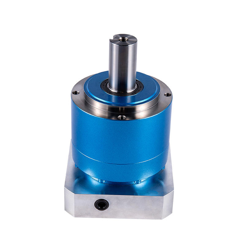
Helical Tooth Transmission Gearbox Planetary Reducer AHL Series for Servo Motor
Cat:Planetary Reducer
Planetary reducers have been widely used in many industries for their performance. Their uniquely de...
See DetailsIn the realm of precision automation, robotics, and high-performance machinery, the seamless conversion of motor speed into usable torque is paramount. At the heart of this conversion lies a critical component: the gear reducer. Among various types, the Planetary Gear Reducer stands out for its exceptional power density, compact footprint, and high efficiency, making it the preferred choice for demanding applications. Understanding the planetary gear reducer working principle is the first step in leveraging its capabilities. However, proper integration requires deeper knowledge, such as how to choose planetary gear reducer size for your specific load and speed requirements, and knowing how it stacks up against alternatives in a planetary gear reducer vs harmonic drive comparison. Furthermore, ensuring long-term performance involves maintenance skills like planetary gear reducer backlash adjustment and effective planetary gear reducer noise troubleshooting. This comprehensive guide delves into all these aspects, providing engineers, designers, and maintenance professionals with the technical depth needed to specify, apply, and maintain these sophisticated mechanical systems effectively. By mastering these concepts, you can optimize your machinery for reliability, precision, and longevity.
Content
The ingenious design of a Planetary Gear Reducer, also known as an epicyclic gearbox, derives its name from its resemblance to a planetary solar system. Its operation is based on the synergistic interaction of four key components arranged concentrically. This configuration allows for torque multiplication and speed reduction within an extremely space-efficient package. The magic lies in the distribution of load across multiple planet gears, which enables high torque transmission while minimizing the size and weight of the unit. The fundamental planetary gear reducer working principle involves one component being held stationary, another serving as the input, and the third becoming the output. By changing which component fulfills each role, different gear ratios and even direction of rotation can be achieved, though the most common configuration for reduction is with the sun gear as input, the carrier as output, and the ring gear fixed.
In the standard reduction stage, power enters via the sun gear. As it rotates, it drives the planet gears, which roll along the inside of the fixed ring gear. This rolling action causes the planet gears to orbit around the sun gear, which in turn rotates the planet carrier. The reduction ratio is determined by the number of teeth on the gears. A basic formula for a simple planetary set with a fixed ring gear is: Reduction Ratio = 1 + (Number of Ring Gear Teeth / Number of Sun Gear Teeth). This design inherently provides high ratios in a single stage.
Selecting the correct Planetary Gear Reducer is a systematic engineering process critical to system performance and lifespan. The question of how to choose planetary gear reducer size cannot be answered by physical dimensions alone; it requires a careful analysis of application demands. An undersized reducer will fail prematurely due to overload, while an oversized unit is unnecessarily costly, bulky, and may operate inefficiently at lower torque levels. The selection process involves defining precise operational parameters, understanding the nuances of manufacturer specifications, and applying appropriate safety margins. This section provides a framework to navigate this crucial decision, ensuring the chosen reducer meets both the immediate performance needs and the long-term reliability goals of your application.
When ultra-high precision and compactness are paramount, engineers often evaluate the planetary gear reducer vs harmonic drive comparison. Both are premier solutions for precision motion control but are based on fundamentally different technologies. A harmonic drive uses a flexible spline, wave generator, and circular spline to achieve motion through elastic deformation, offering exceptionally high single-stage ratios and near-zero backlash. In contrast, a Planetary Gear Reducer operates on rigid body mechanics with rolling contact between metal gears. This core difference leads to a distinct set of performance trade-offs. Planetary gearboxes generally offer higher torsional stiffness, greater torque density, better suitability for high shock loads, and often higher efficiency, but typically at the expense of slightly higher inherent backlash. The choice is not about superiority but about aligning technology strengths with application priorities.
| Aspect | Planetary Gear Reducer | Harmonic Drive |
| Operating Principle | Rigid body mechanics, rolling contact | Elastic mechanics, controlled deformation |
| Single-Stage Ratio Range | ~3:1 to 10:1 (higher with multiple stages) | ~50:1 to 160:1 |
| Torsional Stiffness | Very High | High, but lower than planetary |
| Backlash | Low to medium (arc-minutes) | Extremely low (arc-minutes to zero) |
| Torque Density | Very High | High |
| Efficiency | High (>90% per stage) | Good (~80-90%) |
| Shock Load Resistance | Excellent | Fair to Good (risk to flexspline) |
| Primary Cost | Moderate to High | High |
To preserve the precision and longevity of a Planetary Gear Reducer, proactive maintenance is essential. Two of the most critical aspects are managing gear play and diagnosing acoustic anomalies. Planetary gear reducer backlash adjustment is a precision task that may be required over time as components experience initial wear-in or after prolonged use. Backlash that increases beyond specification can degrade positioning accuracy in robotics or CNC equipment. Simultaneously, abnormal sounds are often the first indicator of a problem. Effective planetary gear reducer noise troubleshooting involves correlating specific noise types—such as a high-pitched whine, a grinding sound, or intermittent knocking—with potential root causes like lubrication issues, misalignment, bearing wear, or gear damage. A systematic approach to these maintenance areas can prevent minor issues from escalating into catastrophic failures.
Backlash is the slight angular movement of the output shaft when the input direction is reversed while the output is held stationary. In precision systems, excessive backlash causes positional error, system instability, and can lead to vibration and accelerated wear.
The service life of a Planetary Gear Reducer is highly variable, typically ranging from 10,000 to over 30,000 hours of operation under proper conditions. Lifespan is primarily determined by the applied load relative to its rated capacity (the service factor), the quality of installation (especially alignment), the maintenance of proper lubrication, and the operating environment (temperature, contaminants). A unit operating well within its rated torque with clean lubrication in a cool environment can far exceed the nominal B10 life rating.
Most modern Planetary Gear Reducers are designed to operate in any orientation. However, this depends on the lubrication system. Units with grease lubrication are generally orientation-agnostic. Those with oil lubrication may have specific port locations for filling and venting, and the oil sump design must be suitable for the mounting angle. Always consult the manufacturer's manual to confirm the approved mounting positions for a specific model.
Lubrication change intervals are not universal. For grease-lubricated reducers in standard service, initial change is recommended after the first 500-2,000 hours of run-in, followed by changes every 5,000 to 20,000 hours. Oil-lubricated units might have similar or shorter intervals. The interval is drastically shortened by high temperatures, heavy loads, frequent start-stop cycles, or dusty/moist environments. Regular inspection of the lubricant's color and consistency is the best guide.
The difference lies in the gear tooth design. Straight-cut (spur) planetary gears have teeth parallel to the shaft axis. They are efficient and easier to manufacture but can be noisier and have slightly lower load capacity. Helical planetary gears have teeth cut at an angle to the axis. This allows for smoother, quieter engagement with more teeth in contact at any given time, resulting in higher torque capacity and reduced vibration. Helical designs are common in applications requiring high precision and low noise.
Not necessarily. A higher service factor indicates a stronger, more robust gearbox with a greater safety margin. While this is beneficial for applications with unpredictable shock loads, it often comes with increased size, weight, and cost. For a well-defined, steady-load application, selecting a reducer with the appropriately matched service factor (e.g., SF=1.0 or 1.2) is more cost-effective and space-efficient than over-specifying with an unnecessarily high SF.
Planetary reducers have been widely used in many industries for their performance. Their uniquely de...
See Details
Planetary reducers occupy an important position in the field of industrial automation. The high-prec...
See Details
With its high-precision characteristics, the planetary reducer successfully controls the backlash wi...
See Details
The planetary reducer adopts a helical gear design, which enables smooth and quiet operation and pro...
See Details
Features of planetary reducer1. Quiet: Use helical gears to achieve smooth and quiet operation;2. Hi...
See Details
● Various output shaft options● High torque● High efficiency● Long service life● Low backlash● Maint...
See Details
In order to meet the needs of different working conditions, the TD-2P series reducer provides a vari...
See Details
The BCSF series Flexible gear reducer pursues the ultimate lightness and simplicity in design, which...
See Details
The BCSG series Flexible gear reducer is designed to be light and simple, which not only effectively...
See Details
BSHF series Flexible gear reducer adopts a large-diameter hollow shaft design with a compact structu...
See Details
