 EN
EN


 English
 русский
 日本語
日本語 Español
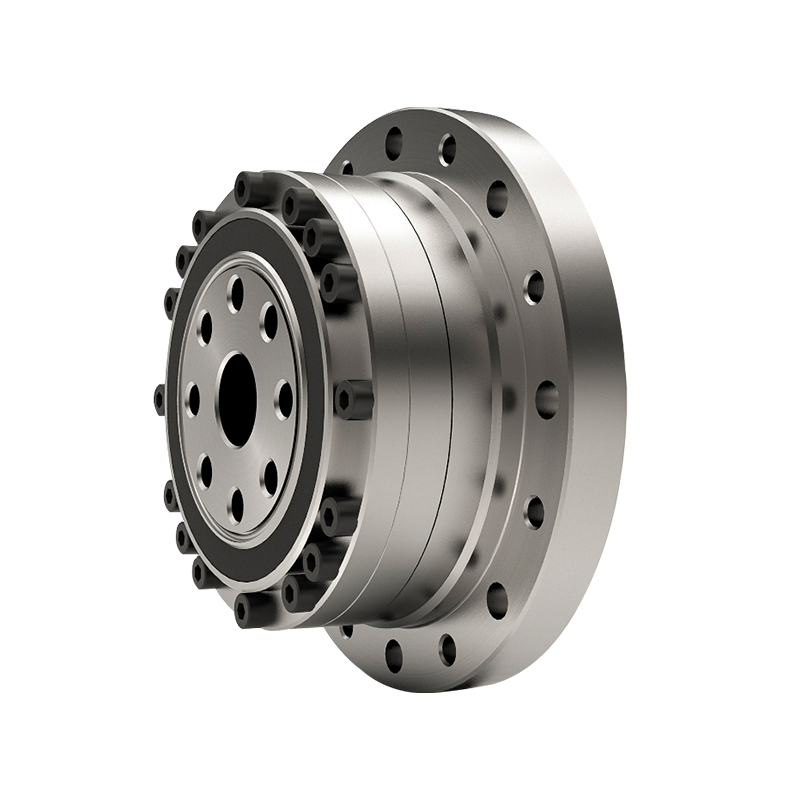
Low Backlash High Precision Torque AHB Planetary Gearbox Reducer
Cat:Planetary Reducer
Features of planetary reducer 1. Quiet: Use helical gears to achieve smooth and quiet operation;2. H...
See DetailsIndustrial drive systems require precise power transmission. A planet gear speed reducer provides high torque output while maintaining a compact footprint. Engineers frequently select these units for heavy-duty applications. The internal gear arrangement allows for excellent power density. This mechanism distributes load across multiple gears. As a result, the system handles high shock loads effectively. Wholesale buyers prioritize these units for their reliability in continuous operations.
Content
The design relies on three main elements. The sun gear sits at the center. Planet gears rotate around the sun gear. The ring gear encloses the entire assembly. This structure creates multiple contact points during power transmission. The distribution of force reduces stress on individual teeth. Manufacturers use high-grade alloy steel for these components. Carburizing and quenching processes harden the gear surfaces. This heat treatment extends the operational lifespan of the unit.
Procurement specialists must evaluate several technical parameters. The selection process directly impacts system efficiency. Buyers need to match the reducer specifications to the application requirements.
Engineers determine the required output torque by analyzing the load profile. The formula multiplies the input power by the gear ratio and efficiency, then divides by the output speed. Users must account for the service factor. The service factor compensates for dynamic loads and frequent starts. Different industries require different service factors. A conveyor application has a lower service factor than a crusher application.
The gear ratio determines the speed reduction and torque multiplication. Most industrial models offer a wide spectrum of ratios. A single-stage unit typically provides a ratio between 3 and 10. Multi-stage configurations achieve much higher reductions.
The gear ratio directly influences the final output speed. Buyers must calculate the exact output speed needed for their machinery. Different ratio stages offer distinct mechanical advantages.
| Stage Configuration | Typical Ratio Range | Efficiency Level |
| Single Stage | 3:1 to 10:1 | 97% - 99% |
| Two Stage | 15:1 to 100:1 | 94% - 97% |
| Three Stage | 100:1 to 500:1 | 91% - 94% |
Buyers often compare these two popular configurations. An inline planetary unit shares a common centerline with the motor. A helical gearbox usually features offset parallel shafts. The inline design saves physical space. The planetary design also handles higher radial loads due to the multiple gear contacts.
| Feature | Inline Planetary | Helical Gearbox |
| Shaft Alignment | Coaxial | Parallel Offset |
| Size to Torque Ratio | Compact | Larger |
| Load Distribution | Multiple Points | Single Point |
Long-term operation depends on internal durability. Mechanical efficiency remains a critical metric for bulk buyers. High efficiency reduces energy consumption over the equipment lifecycle.
Efficiency measures the power loss during transmission. Planetary gears generally exhibit very low friction losses. The rolling contact between gear teeth minimizes heat generation. Efficiency ratings typically range from 95 percent to 99 percent, depending on the number of stages. Higher efficiency translates to lower electrical costs for the facility. It also means the gearbox runs cooler. Reduced heat extends the life of the lubricant and the bearings.
Industrial facilities have strict noise regulations. Gear whine is a common issue in power transmission. Planetary systems inherently produce less noise than other types. The symmetrical design cancels out many internal forces. Precision machining of the gear teeth further lowers acoustic emissions. Ground tooth profiles ensure smooth meshing. Manufacturers also use specialized housing designs to dampen vibrations. Proper lubrication with synthetic oils significantly reduces operational noise.
Correct installation guarantees the rated performance. Alignment is crucial for inline models. Misalignment causes premature bearing failure. Maintenance teams should monitor vibration signatures regularly. Oil analysis detects early signs of wear particles. Replacing the lubricant at scheduled intervals prevents component degradation.

Features of planetary reducer 1. Quiet: Use helical gears to achieve smooth and quiet operation;2. H...
See Details
Planetary reducers have been widely used in many industries for their performance. Their uniquely de...
See Details
With its high-precision characteristics, the planetary reducer successfully controls the backlash wi...
See Details
Our reducers incorporate the cutting-edge design concept of helical gears. Compared with traditional...
See Details
The NHT series planetary reducer adopts an advanced helical gear design, which not only significantl...
See Details
1. Helical gear designThe speed reduction mechanism adopts a helical gear design, and its tooth mesh...
See Details
The NLR series planetary reducer adopts a spiral bevel gear design, which allows high-speed input of...
See Details
The NSR series planetary reducer adopts a spiral bevel gear design. This innovation not only makes t...
See Details
NTR series planetary reducer adopts spiral bevel gear design, which allows high-speed input of servo...
See Details
BSHF series Flexible gear reducer adopts a large-diameter hollow shaft design with a compact structu...
See Details
