 EN
EN


 English
 русский
 日本語
日本語 Español
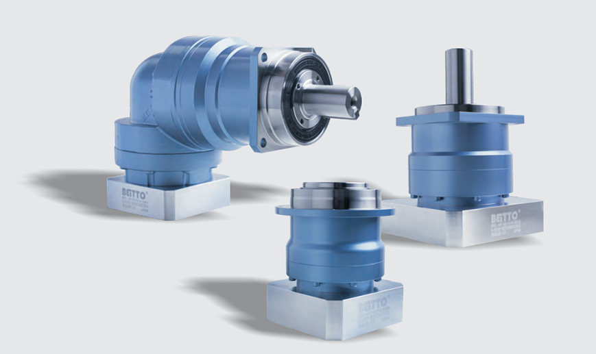
Low Noise Multi specification Integrated-Structure Planetary Reducer AHS Series
Cat:Planetary Reducer
Planetary reducers occupy an important position in the field of industrial automation. The high-prec...
See DetailsSelecting a planetary gear reducer for an industrial drive system is a decision that affects torque density, positional accuracy, service life, and total drivetrain cost. Unlike parallel-axis or worm gear reducers, the planetary architecture distributes load across multiple planet gears simultaneously, achieving a combination of high torque capacity, compact axial length, and coaxial input-output alignment that no other single-stage gear topology can match. This guide gives procurement engineers and wholesale buyers the technical framework to evaluate, specify, and source planetary reducers with confidence.
Content
A planetary gear set consists of three concentric elements: a central sun gear, an outer ring gear (also called the annulus), and a set of planet gears mounted on a rotating carrier. The input shaft typically drives the sun gear. The planet gears mesh simultaneously with the sun gear and the ring gear. The output is taken from the planet carrier while the ring gear is held stationary. This arrangement creates a compact, symmetrical load path that defines the mechanical advantages of the planetgear speed reducer architecture.
The number of planet gears in a single stage is typically three or four. Three-planet designs are standard in most industrial reducers. Four-planet designs appear in high-load applications where maximizing torque density per stage is critical. Each additional planet gear proportionally shares the total transmitted torque, which reduces individual gear tooth stress and extends contact fatigue life.
The load-sharing principle is the primary reason planetary reducers achieve higher torque density than equivalent-size parallel-axis gearboxes. In a three-planet stage, each planet gear carries approximately one-third of the total transmitted torque. This distributes Hertzian contact stress across six gear meshes per stage (three sun-planet meshes and three planet-ring meshes), compared to two meshes in a single helical gear stage. The result is a substantially higher torque-to-weight ratio for the same material and module specification.
A correct planetary gear reducer ratio selection guide starts with defining output speed and output torque requirements from the application load cycle, then working backward to select input motor speed and frame size. The ratio of a single planetary stage is defined by the number of teeth on the ring gear and the sun gear. For a fixed ring gear configuration, the ratio R = (Zring / Zsun) + 1, where Zring is the number of ring gear teeth and Zsun is the number of sun gear teeth.
Single-stage planetary reducers typically achieve ratios from 3:1 to 10:1. Two-stage designs extend the range to approximately 9:1 to 100:1. Three-stage configurations reach ratios up to 512:1 in standard catalog products. The table below maps ratio ranges to stage count and typical application categories.
| Ratio Range | Stage Count | Typical Input Speed (rpm) | Primary Application |
|---|---|---|---|
| 3:1 to 10:1 | Single stage | 1,000–6,000 | Servo axes, conveyors, light robotics |
| 9:1 to 100:1 | Two stage | 1,000–5,000 | CNC machine tools, packaging machinery |
| 81:1 to 512:1 | Three stage | 1,000–3,000 | Heavy automation, AGV drives, hoisting |
Buyers should avoid selecting a ratio at the extreme end of a stage count range, as efficiency and backlash performance both degrade toward the limits of each stage configuration. A two-stage unit at a 50:1 ratio delivers better efficiency than a three-stage unit at the same ratio.
The planetary gear speed reducer torque and efficiency specs that appear in supplier catalogs require careful interpretation. Rated output torque refers to the continuous torque the reducer can transmit without exceeding thermal limits or surface fatigue life over a defined service interval — typically 20,000 hours at a stated input speed and ambient temperature. Peak torque (also called emergency or acceleration torque) is typically 2 to 3 times the rated value and is permissible only for brief, infrequent cycles.
| Parameter | Single Stage | Two Stage | Three Stage |
|---|---|---|---|
| Typical mechanical efficiency | 97–98% | 94–96% | 91–94% |
| Rated output torque range (Nm) | 10–2,000 | 20–5,000 | 50–10,000+ |
| Max input speed (rpm) | Up to 6,000 | Up to 5,000 | Up to 3,000 |
| Radial load capacity | Moderate | High | Very high |
| Thermal power loss per stage | 2–3% | 4–6% | 6–9% |
Mechanical efficiency figures are measured at full rated load and nominal input speed. Efficiency drops at partial load conditions because constant-friction losses (bearing drag, seal drag, churning losses in lubricated housings) represent a larger proportion of transmitted power at reduced torque. Buyers specifying reducers for variable-duty cycles should request efficiency curves across the full load range, not just peak-efficiency values.
The comparison between an inline planetary gear reducer vs helical gear reducer is one of the most common specification decisions in industrial drivetrain engineering. Both architectures are capable of high efficiency and long service life, but they differ substantially in torque density, physical envelope, backlash characteristics, and cost structure. The table below summarizes the key differences across parameters relevant to B2B procurement.
| Parameter | Inline Planetary Gear Reducer | Parallel-Axis Helical Gear Reducer |
|---|---|---|
| Torque density | Very high (coaxial load sharing) | Moderate |
| Physical envelope | Compact, short axial length | Larger, offset input/output shafts |
| Input/output alignment | Coaxial (inline) | Parallel offset or right-angle |
| Typical efficiency per stage | 97–98% | 98–99% |
| Backlash (standard grade) | 3–8 arcmin | 8–20 arcmin |
| Backlash (precision grade) | 1–3 arcmin | 3–8 arcmin |
| Noise level | Low to moderate | Low (helical tooth contact) |
| Unit cost (equivalent torque) | Higher | Lower |
| Best-fit application | Servo systems, robotics, precision automation | Conveyor drives, fans, pumps |
Helical reducers offer marginally higher single-stage efficiency due to the absence of simultaneous multi-mesh engagement losses, but they cannot match the torque density or backlash performance of a well-designed planetary stage at the same frame size.
Planetary gear reducer backlash and precision grades are the dominant selection criteria for motion control and servo drive applications. Backlash is defined as the total angular rotation of the output shaft when the input is held stationary and the output is loaded in alternating directions. It is expressed in arcminutes (arcmin). One arcmin equals 1/60 of one degree.
ISO and DIN standards classify planetary reducers into precision grades based on backlash thresholds:
Backlash increases with each additional reduction stage. A single-stage precision-grade reducer at 3 arcmin combined with a second-stage unit at 3 arcmin does not produce 3 arcmin at the final output — the second stage backlash is reflected to the output at the first-stage ratio, and the contributions add. Buyers specifying multi-stage precision drives must evaluate system-level backlash, not individual stage values.
For buyers evaluating planetary gear reducer wholesale MOQ and pricing, market pricing is segmented by frame size (flange diameter in mm), ratio, precision grade, and output shaft configuration. Standard-grade inline planetary reducers in common frame sizes (60 mm, 80 mm, 120 mm flange) are widely available with MOQs of 10 to 50 units per SKU from volume manufacturers. Precision-grade and high-precision units carry higher unit costs and typically require MOQs of 5 to 20 units with longer lead times due to selective assembly requirements.
Wholesale qualification documentation for a planetary gear reducer procurement program should include the following:
A planetary gear reducer uses a coaxial arrangement of sun gear, planet gears, and ring gear to distribute torque across multiple simultaneous gear meshes. A standard parallel-axis gearbox transmits torque through a single pair of meshing gears per stage. The planetary design achieves significantly higher torque density, lower backlash, and more compact dimensions at equivalent torque ratings. The trade-off is higher manufacturing complexity and unit cost compared to a parallel-axis unit of the same ratio.
The theoretical output torque of a planetgear speed reducer equals the input torque multiplied by the gear ratio and multiplied by the stage efficiency. For a two-stage reducer with an overall ratio of 25:1 and a total efficiency of 95%, an input torque of 10 Nm produces a theoretical output torque of 10 x 25 x 0.95 = 237.5 Nm. In practice, buyers should verify that this calculated value does not exceed the reducer's rated continuous output torque as stated in the manufacturer's specification sheet, since thermal limits may be more restrictive than gear strength limits at continuous duty.
CNC servo axis applications typically require backlash below 5 arcmin for standard machining centers and below 3 arcmin for precision grinding or boring machines. High-precision contouring applications may require backlash below 1 arcmin. The acceptable level depends on the axis resolution, the distance from the reducer output to the tool contact point, and the contouring accuracy specification of the machine. Buyers should calculate the linear positional error introduced by the backlash at the toolpoint distance and compare it against the machine's stated positional accuracy tolerance.
Most industrial-grade planetary reducers are designed for a minimum L10 bearing life of 20,000 hours at rated load and rated input speed, which corresponds to approximately 8–10 years of single-shift operation. Actual service life depends on operating torque as a fraction of rated torque, input speed, ambient temperature, lubrication condition, and shock load frequency. Reducers operating at 70% of rated torque and nominal speed in clean, temperature-controlled environments routinely achieve 30,000 to 50,000 hours before requiring overhaul. Buyers should request the L10h calculation from suppliers, specifying the actual application load cycle, not the catalog rated conditions.

Planetary reducers occupy an important position in the field of industrial automation. The high-prec...
See Details
The planetary reducer adopts a helical gear design, which enables smooth and quiet operation and pro...
See Details
Features of planetary reducer1. High precision: the standard backlash is 4 arc minutes, which is ver...
See Details
Designed for applications with high radial loads, such as AGV wheel drives, pulley drives. Output op...
See Details
● Various output shaft options● High torque● High efficiency● Long service life● Low backlash● Maint...
See Details
1. Helical gear designThe speed reduction mechanism adopts a helical gear design, and its tooth mesh...
See Details
Innovative helical gear structureThe reduction mechanism introduces an innovative helical gear desig...
See Details
NTR series planetary reducer adopts spiral bevel gear design, which allows high-speed input of servo...
See Details
The BCSG series Flexible gear reducer is designed to be light and simple, which not only effectively...
See Details
BSHF series Flexible gear reducer adopts a large-diameter hollow shaft design with a compact structu...
See Details
